
An I2C scanner is one of the more useful diagnostic programs to keep alongside an ATmega4809 project. Instead of communicating with a particular sensor or display, the program works through the usable 7-bit I2C address range and checks whether a device acknowledges each address.
The result is a simple list of the devices that are actually responding on the bus. This can save a considerable amount of time when connecting an unfamiliar module, especially when the address printed in an example or product listing does not match the hardware in front of you.
The scanner is particularly useful before developing a driver for a new I2C device. If a sensor expected at 0x44 appears at that address, there is already evidence that it has power, the bus is operating and the device can respond to the ATmega4809.
If nothing appears, there is little value in immediately debugging conversion formulas or sensor registers. The problem is more likely to be lower down the chain: SDA and SCL may be reversed, the device may not be powered correctly, pull-up resistors may be missing, or the TWI peripheral may not have been configured as expected.
Addresses should normally be displayed as 7-bit values. This avoids a common source of confusion when working from datasheets or older code that describes an I2C address after it has been shifted to make room for the read/write bit.
An address such as 0x38, for example, should normally be treated as 0x38 by the application, with the TWI hardware or low-level driver handling whether the transaction is a read or a write.
If an expected device appears at what seems to be twice its documented address, checking whether 7-bit and 8-bit address notation has been mixed is worthwhile.
A working scanner is also useful when several devices share the same bus.
An OLED, temperature sensor, GPIO expander and EEPROM can all use the same SDA and SCL connections provided their addresses do not conflict and the electrical characteristics of the bus remain suitable.
Running the scanner after adding each device gives a quick indication that the existing devices are still responding and that the new one has appeared where expected. It can also expose address conflicts before they become harder to diagnose in the main application.
A general scanner should concentrate on the normal peripheral-address region and avoid reserved I2C addresses. It should also distinguish between an acknowledgement and a completed device transaction: discovering an address only proves that something responds there. It does not identify the device or confirm that its measurement, configuration or data registers are working correctly.
Once the scanner is reliable, it becomes a useful test of the ATmega4809 TWI code itself. If a new I2C project fails, returning to the scanner can quickly separate a basic bus problem from an error in the device-specific driver.
That makes the scanner worth keeping as a permanent diagnostic project rather than treating it as a one-off example.
Code
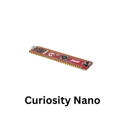
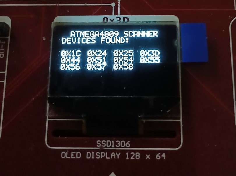
This is a complete, standalone I2C bus scanner for the ATmega4809 Curiosity Nano. It checks addresses from 0x08 to 0x77, formats discovered devices into a multi-column grid on the SSD1306 OLED (at address 0x3D), and toggles the onboard LED (PF5) during scanning.
#define F_CPU 3333333UL // Default ATmega4809 clock speed (20MHz / 6)
#include <avr/io.h>
#include <util/delay.h>

#define SSD1306_I2C_ADDR 0x3D
#define HEARTBEAT_LED_MASK PIN5_bm // PF5 Onboard LED

// --- Font Table (ASCII 32 to 90: ' ' through 'Z') ---
const uint8_t FONT_5x7[][5] = {
    {0x00, 0x00, 0x00, 0x00, 0x00}, // ' '
    {0x00, 0x00, 0x5F, 0x00, 0x00}, // '!'
    {0x00, 0x07, 0x00, 0x07, 0x00}, // '"'
    {0x14, 0x7F, 0x14, 0x7F, 0x14}, // '#'
    {0x24, 0x2A, 0x7F, 0x2A, 0x12}, // '$'
    {0x23, 0x13, 0x08, 0x64, 0x62}, // '%'
    {0x36, 0x49, 0x55, 0x22, 0x50}, // '&'
    {0x00, 0x05, 0x03, 0x00, 0x00}, // '\''
    {0x00, 0x1C, 0x22, 0x41, 0x00}, // '('
    {0x00, 0x41, 0x22, 0x1C, 0x00}, // ')'
    {0x14, 0x08, 0x3E, 0x08, 0x14}, // '*'
    {0x08, 0x08, 0x3E, 0x08, 0x08}, // '+'
    {0x00, 0x50, 0x30, 0x00, 0x00}, // ','
    {0x08, 0x08, 0x08, 0x08, 0x08}, // '-'
    {0x00, 0x60, 0x60, 0x00, 0x00}, // '.'
    {0x20, 0x10, 0x08, 0x04, 0x02}, // '/'
    {0x3E, 0x51, 0x49, 0x45, 0x3E}, // '0'
    {0x00, 0x42, 0x7F, 0x40, 0x00}, // '1'
    {0x42, 0x61, 0x51, 0x49, 0x46}, // '2'
    {0x21, 0x41, 0x45, 0x4B, 0x31}, // '3'
    {0x18, 0x14, 0x12, 0x7F, 0x10}, // '4'
    {0x27, 0x45, 0x45, 0x45, 0x39}, // '5'
    {0x3C, 0x4A, 0x49, 0x49, 0x30}, // '6'
    {0x01, 0x71, 0x09, 0x05, 0x03}, // '7'
    {0x36, 0x49, 0x49, 0x49, 0x36}, // '8'
    {0x06, 0x49, 0x49, 0x29, 0x1E}, // '9'
    {0x00, 0x36, 0x36, 0x00, 0x00}, // ':'
    {0x00, 0x56, 0x36, 0x00, 0x00}, // ';'
    {0x08, 0x14, 0x22, 0x41, 0x00}, // '<'
    {0x14, 0x14, 0x14, 0x14, 0x14}, // '='
    {0x00, 0x41, 0x22, 0x14, 0x08}, // '>'
    {0x02, 0x01, 0x51, 0x09, 0x06}, // '?'
    {0x32, 0x49, 0x79, 0x41, 0x3E}, // '@'
    {0x7E, 0x11, 0x11, 0x11, 0x7E}, // 'A'
    {0x7F, 0x49, 0x49, 0x49, 0x36}, // 'B'
    {0x3E, 0x41, 0x41, 0x41, 0x22}, // 'C'
    {0x7F, 0x41, 0x41, 0x22, 0x1C}, // 'D'
    {0x7F, 0x49, 0x49, 0x49, 0x41}, // 'E'
    {0x7F, 0x09, 0x09, 0x09, 0x01}, // 'F'
    {0x3E, 0x41, 0x49, 0x49, 0x7A}, // 'G'
    {0x7F, 0x08, 0x08, 0x08, 0x7F}, // 'H'
    {0x00, 0x41, 0x7F, 0x41, 0x00}, // 'I'
    {0x20, 0x40, 0x41, 0x3F, 0x01}, // 'J'
    {0x7F, 0x08, 0x14, 0x22, 0x41}, // 'K'
    {0x7F, 0x40, 0x40, 0x40, 0x40}, // 'L'
    {0x7F, 0x02, 0x0C, 0x02, 0x7F}, // 'M'
    {0x7F, 0x04, 0x08, 0x10, 0x7F}, // 'N'
    {0x3E, 0x41, 0x41, 0x41, 0x3E}, // 'O'
    {0x7F, 0x09, 0x09, 0x09, 0x06}, // 'P'
    {0x3E, 0x41, 0x51, 0x21, 0x5E}, // 'Q'
    {0x7F, 0x09, 0x19, 0x29, 0x46}, // 'R'
    {0x46, 0x49, 0x49, 0x49, 0x31}, // 'S'
    {0x01, 0x01, 0x7F, 0x01, 0x01}, // 'T'
    {0x3F, 0x40, 0x40, 0x40, 0x3F}, // 'U'
    {0x1F, 0x20, 0x40, 0x20, 0x1F}, // 'V'
    {0x3F, 0x40, 0x38, 0x40, 0x3F}, // 'W'
    {0x63, 0x14, 0x08, 0x14, 0x63}, // 'X'
    {0x07, 0x08, 0x70, 0x08, 0x07}, // 'Y'
    {0x61, 0x51, 0x49, 0x45, 0x43}  // 'Z'
};

// --- Bare-Metal I2C Driver ---
void TWI0_Init(void) {
    PORTA.DIRCLR = PIN2_bm | PIN3_bm;
    PORTA.PIN2CTRL = PORT_PULLUPEN_bm; // PA2 SDA
    PORTA.PIN3CTRL = PORT_PULLUPEN_bm; // PA3 SCL

    TWI0.MBAUD = 12; // ~100 kHz clock
    TWI0.MCTRLA = TWI_ENABLE_bm;
    TWI0.MSTATUS = TWI_BUSSTATE_IDLE_gc;
}

uint8_t TWI0_Start(uint8_t addr_rw) {
    TWI0.MADDR = addr_rw;
    while (!(TWI0.MSTATUS & (TWI_RIF_bm | TWI_WIF_bm)));

    if (TWI0.MSTATUS & TWI_RXACK_bm) { // NACK received (no device at address)
        TWI0.MCTRLB = TWI_MCMD_STOP_gc;
        return 0;
    }
    return 1; // ACK received
}

uint8_t TWI0_Write(uint8_t data) {
    TWI0.MDATA = data;
    while (!(TWI0.MSTATUS & TWI_WIF_bm));

    if (TWI0.MSTATUS & TWI_RXACK_bm) {
        return 0;
    }
    return 1;
}

void TWI0_Stop(void) {
    TWI0.MCTRLB = TWI_MCMD_STOP_gc;
}

// --- SSD1306 Display ---
void SSD1306_Command(uint8_t cmd) {
    TWI0_Start((SSD1306_I2C_ADDR << 1) | 0);
    TWI0_Write(0x00);
    TWI0_Write(cmd);
    TWI0_Stop();
}

void SSD1306_Data(uint8_t data) {
    TWI0_Start((SSD1306_I2C_ADDR << 1) | 0);
    TWI0_Write(0x40);
    TWI0_Write(data);
    TWI0_Stop();
}

void SSD1306_Init(void) {
    _delay_ms(100);
    SSD1306_Command(0xAE);
    SSD1306_Command(0xD5); SSD1306_Command(0x80);
    SSD1306_Command(0xA8); SSD1306_Command(0x3F);
    SSD1306_Command(0xD3); SSD1306_Command(0x00);
    SSD1306_Command(0x40);
    SSD1306_Command(0x8D); SSD1306_Command(0x14);
    SSD1306_Command(0x20); SSD1306_Command(0x00);
    SSD1306_Command(0xA1);
    SSD1306_Command(0xC8);
    SSD1306_Command(0xDA); SSD1306_Command(0x12);
    SSD1306_Command(0x81); SSD1306_Command(0xCF);
    SSD1306_Command(0xD9); SSD1306_Command(0xF1);
    SSD1306_Command(0xDB); SSD1306_Command(0x40);
    SSD1306_Command(0xA4);
    SSD1306_Command(0xA6);
    SSD1306_Command(0xAF);
}

void SSD1306_Clear(void) {
    for (uint8_t page = 0; page < 8; page++) {
        SSD1306_Command(0xB0 + page);
        SSD1306_Command(0x00);
        SSD1306_Command(0x10);
        for (uint8_t col = 0; col < 128; col++) {
            SSD1306_Data(0x00);
        }
    }
}

void SSD1306_DrawChar(char c, uint8_t page, uint8_t col) {
    if (c >= 'a' && c <= 'z') c -= 32;
    if (c < 32 || c > 90) c = ' ';

    uint8_t font_index = c - 32;

    SSD1306_Command(0xB0 + page);
    SSD1306_Command(0x00 + (col & 0x0F));
    SSD1306_Command(0x10 + ((col >> 4) & 0x0F));

    for (uint8_t i = 0; i < 5; i++) {
        SSD1306_Data(FONT_5x7[font_index][i]);
    }
    SSD1306_Data(0x00);
}

void SSD1306_DrawString(const char *str, uint8_t page, uint8_t col) {
    while (*str && col < 122) {
        SSD1306_DrawChar(*str++, page, col);
        col += 6;
    }
}

void ByteToHexStr(uint8_t val, char *buf) {
    const char hexDigits[] = "0123456789ABCDEF";
    buf[0] = hexDigits[(val >> 4) & 0x0F];
    buf[1] = hexDigits[val & 0x0F];
    buf[2] = '\0';
}

int main(void) {
    PORTF.DIRSET = HEARTBEAT_LED_MASK;
    PORTF.OUTSET = HEARTBEAT_LED_MASK;

    TWI0_Init();
    SSD1306_Init();
    SSD1306_Clear();

    SSD1306_DrawString("ATMEGA4809 SCANNER", 0, 10);
    SSD1306_DrawString("DEVICES FOUND:", 1, 0);

    uint8_t foundCount = 0;
    uint8_t page = 3;
    uint8_t col = 0;
    char hexBuf[3];

    for (uint8_t addr = 0x08; addr <= 0x77; addr++) {
        // write bit
        if (TWI0_Start((addr << 1) | 0)) {
            TWI0_Stop(); // Acknowledged! Device present

            ByteToHexStr(addr, hexBuf);

            // Display in grid format (4 items per page row)
            SSD1306_DrawString("0X", page, col);
            SSD1306_DrawString(hexBuf, page, col + 12);

            foundCount++;
            col += 32;

            if (col >= 128) {
                col = 0;
                page += 1;
                if (page > 7) break; // Exceeded display rows
            }
        }

        PORTF.OUTTGL = HEARTBEAT_LED_MASK;
        _delay_ms(10);
    }

    if (foundCount == 0) {
        SSD1306_DrawString("NO DEVICES FOUND", 4, 16);
    }

    while (1) {
        PORTF.OUTTGL = HEARTBEAT_LED_MASK;
        _delay_ms(500);
    }

    return 0;
}
Image
i2scanner