
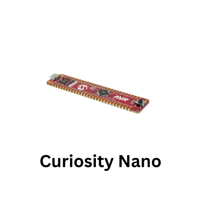
The MCP23008 adds eight individually configurable digital I/O lines to the ATmega4809 while requiring only the existing I2C bus. This is particularly useful when a design begins to run short of GPIO because of displays, sensors, switches, status LEDs or control signals.
Multiple I2C peripherals can share the same SDA and SCL lines, so adding the MCP23008 does not require eight additional connections to the microcontroller.
Each of the eight GP0 to GP7 pins can independently operate as an input or output. The IODIR register determines the direction of the complete eight-bit port, with a 1 configuring the corresponding pin as an input and a 0 selecting an output. This makes configurations such as four inputs and four outputs possible without additional hardware.
Output control is handled through the GPIO and OLAT registers. OLAT represents the output latch, making it useful when firmware needs to construct or modify an output pattern before writing it to the expander. A single byte can control all eight outputs, which is particularly convenient for LED banks, binary indicators and control signals.
When individual outputs need to change without disturbing the others, the firmware can maintain a local copy of the output state, modify the required bit and write the updated byte.
The MCP23008 provides considerably more than simple output expansion. Input pins can use individually enabled internal pull-up resistors through GPPU, reducing the external components required for switches and other active-low inputs.
Input polarity can be inverted with IPOL, allowing firmware to change the logical interpretation of an input without modifying the external circuit.
Interrupt-on-change support is especially useful when the MCP23008 is used for inputs. The GPINTEN, INTCON and DEFVAL registers allow selected pins to generate an interrupt either when their state changes or when they differ from a predefined value.
The INTF register identifies which input caused the interrupt, while INTCAP captures the GPIO state when the interrupt occurred. Connecting the MCP23008 interrupt output to an ATmega4809 input allows the microcontroller to respond to external changes without continuously polling the expander over I2C.
Three hardware address inputs, A0, A1 and A2, provide eight selectable I2C addresses from 0x20 through 0x27. Up to eight MCP23008 devices can therefore share one bus, providing as many as 64 additional GPIO lines while still using the same ATmega4809 TWI interface.
This also makes address selection worth understanding when several modules or other I2C devices are connected simultaneously.
Setup
- PA2 – I2C Data for MCP23008 & SSD1306)
- PA3 – I2C Clock for MCP23008 & SSD1306)
- PF5 – Onboard Heartbeat LED
Code
This example runs a 4-pattern LED sequence on pins GP0–GP7 (Knight Rider scanner, expanding bar graph, binary counter, and alternating flash) while writing the active mode status to the SSD1306 OLED screen.
#define F_CPU 3333333UL // Default ATmega4809 clock speed (20MHz / 6)
#include <avr/io.h>
#include <util/delay.h>

// I2C 7-Bit Device Addresses
#define EXPANDER_I2C_ADDR 0x25  // MCP23008 Address: 0x25
#define SSD1306_I2C_ADDR  0x3D  // SSD1306 OLED Address

// MCP23008 Registers
#define MCP23008_REG_IODIR 0x00  // I/O Direction Register (0 = Output, 1 = Input)
#define MCP23008_REG_GPIO  0x09  // General Purpose I/O Port Register

// Onboard LED Definition (PF5 on ATmega4809 Nano)
#define HEARTBEAT_LED_MASK PIN5_bm

// --- Font Table (ASCII 32 to 90: ' ' through 'Z') ---
const uint8_t FONT_5x7[][5] = {
    {0x00, 0x00, 0x00, 0x00, 0x00}, // ' '
    {0x00, 0x00, 0x5F, 0x00, 0x00}, // '!'
    {0x00, 0x07, 0x00, 0x07, 0x00}, // '"'
    {0x14, 0x7F, 0x14, 0x7F, 0x14}, // '#'
    {0x24, 0x2A, 0x7F, 0x2A, 0x12}, // '$'
    {0x23, 0x13, 0x08, 0x64, 0x62}, // '%'
    {0x36, 0x49, 0x55, 0x22, 0x50}, // '&'
    {0x00, 0x05, 0x03, 0x00, 0x00}, // '\''
    {0x00, 0x1C, 0x22, 0x41, 0x00}, // '('
    {0x00, 0x41, 0x22, 0x1C, 0x00}, // ')'
    {0x14, 0x08, 0x3E, 0x08, 0x14}, // '*'
    {0x08, 0x08, 0x3E, 0x08, 0x08}, // '+'
    {0x00, 0x50, 0x30, 0x00, 0x00}, // ','
    {0x08, 0x08, 0x08, 0x08, 0x08}, // '-'
    {0x00, 0x60, 0x60, 0x00, 0x00}, // '.'
    {0x20, 0x10, 0x08, 0x04, 0x02}, // '/'
    {0x3E, 0x51, 0x49, 0x45, 0x3E}, // '0'
    {0x00, 0x42, 0x7F, 0x40, 0x00}, // '1'
    {0x42, 0x61, 0x51, 0x49, 0x46}, // '2'
    {0x21, 0x41, 0x45, 0x4B, 0x31}, // '3'
    {0x18, 0x14, 0x12, 0x7F, 0x10}, // '4'
    {0x27, 0x45, 0x45, 0x45, 0x39}, // '5'
    {0x3C, 0x4A, 0x49, 0x49, 0x30}, // '6'
    {0x01, 0x71, 0x09, 0x05, 0x03}, // '7'
    {0x36, 0x49, 0x49, 0x49, 0x36}, // '8'
    {0x06, 0x49, 0x49, 0x29, 0x1E}, // '9'
    {0x00, 0x36, 0x36, 0x00, 0x00}, // ':'
    {0x00, 0x56, 0x36, 0x00, 0x00}, // ';'
    {0x08, 0x14, 0x22, 0x41, 0x00}, // '<'
    {0x14, 0x14, 0x14, 0x14, 0x14}, // '='
    {0x00, 0x41, 0x22, 0x14, 0x08}, // '>'
    {0x02, 0x01, 0x51, 0x09, 0x06}, // '?'
    {0x32, 0x49, 0x79, 0x41, 0x3E}, // '@'
    {0x7E, 0x11, 0x11, 0x11, 0x7E}, // 'A'
    {0x7F, 0x49, 0x49, 0x49, 0x36}, // 'B'
    {0x3E, 0x41, 0x41, 0x41, 0x22}, // 'C'
    {0x7F, 0x41, 0x41, 0x22, 0x1C}, // 'D'
    {0x7F, 0x49, 0x49, 0x49, 0x41}, // 'E'
    {0x7F, 0x09, 0x09, 0x09, 0x01}, // 'F'
    {0x3E, 0x41, 0x49, 0x49, 0x7A}, // 'G'
    {0x7F, 0x08, 0x08, 0x08, 0x7F}, // 'H'
    {0x00, 0x41, 0x7F, 0x41, 0x00}, // 'I'
    {0x20, 0x40, 0x41, 0x3F, 0x01}, // 'J'
    {0x7F, 0x08, 0x14, 0x22, 0x41}, // 'K'
    {0x7F, 0x40, 0x40, 0x40, 0x40}, // 'L'
    {0x7F, 0x02, 0x0C, 0x02, 0x7F}, // 'M'
    {0x7F, 0x04, 0x08, 0x10, 0x7F}, // 'N'
    {0x3E, 0x41, 0x41, 0x41, 0x3E}, // 'O'
    {0x7F, 0x09, 0x09, 0x09, 0x06}, // 'P'
    {0x3E, 0x41, 0x51, 0x21, 0x5E}, // 'Q'
    {0x7F, 0x09, 0x19, 0x29, 0x46}, // 'R'
    {0x46, 0x49, 0x49, 0x49, 0x31}, // 'S'
    {0x01, 0x01, 0x7F, 0x01, 0x01}, // 'T'
    {0x3F, 0x40, 0x40, 0x40, 0x3F}, // 'U'
    {0x1F, 0x20, 0x40, 0x20, 0x1F}, // 'V'
    {0x3F, 0x40, 0x38, 0x40, 0x3F}, // 'W'
    {0x63, 0x14, 0x08, 0x14, 0x63}, // 'X'
    {0x07, 0x08, 0x70, 0x08, 0x07}, // 'Y'
    {0x61, 0x51, 0x49, 0x45, 0x43}  // 'Z'
};

// --- I2C  ---
void TWI0_Init(void) {
    PORTA.DIRCLR = PIN2_bm | PIN3_bm;
    PORTA.PIN2CTRL = PORT_PULLUPEN_bm; // Enable pull-up on PA2 (SDA)
    PORTA.PIN3CTRL = PORT_PULLUPEN_bm; // Enable pull-up on PA3 (SCL)

    TWI0.MBAUD = 12; // ~100 kHz @ 3.33MHz system clock
    TWI0.MCTRLA = TWI_ENABLE_bm;
    TWI0.MSTATUS = TWI_BUSSTATE_IDLE_gc; // Set bus state to IDLE
}

uint8_t TWI0_Start(uint8_t addr_rw) {
    TWI0.MADDR = addr_rw;
    while (!(TWI0.MSTATUS & (TWI_RIF_bm | TWI_WIF_bm)));

    if (TWI0.MSTATUS & TWI_RXACK_bm) { // Check for NACK
        TWI0.MCTRLB = TWI_MCMD_STOP_gc;
        return 0;
    }
    return 1;
}

uint8_t TWI0_Write(uint8_t data) {
    TWI0.MDATA = data;
    while (!(TWI0.MSTATUS & TWI_WIF_bm));

    if (TWI0.MSTATUS & TWI_RXACK_bm) {
        return 0; // NACK
    }
    return 1; // ACK
}

void TWI0_Stop(void) {
    TWI0.MCTRLB = TWI_MCMD_STOP_gc;
}

// --- MCP23008 I/O Expander Driver ---
void Expander_WriteRegister(uint8_t reg, uint8_t value) {
    if (TWI0_Start((EXPANDER_I2C_ADDR << 1) | 0)) {
        TWI0_Write(reg);
        TWI0_Write(value);
        TWI0_Stop();
    }
}

void Expander_Init(void) {
    // Set all 8 pins (GP0-GP7) as Outputs (0x00)
    Expander_WriteRegister(MCP23008_REG_IODIR, 0x00);
    // Turn off all LEDs initially
    Expander_WriteRegister(MCP23008_REG_GPIO, 0x00);
}

void Expander_SetOutputs(uint8_t mask) {
    Expander_WriteRegister(MCP23008_REG_GPIO, mask);
}

// --- SSD1306 OLED   ---
void SSD1306_Command(uint8_t cmd) {
    TWI0_Start((SSD1306_I2C_ADDR << 1) | 0);
    TWI0_Write(0x00);
    TWI0_Write(cmd);
    TWI0_Stop();
}

void SSD1306_Data(uint8_t data) {
    TWI0_Start((SSD1306_I2C_ADDR << 1) | 0);
    TWI0_Write(0x40);
    TWI0_Write(data);
    TWI0_Stop();
}

void SSD1306_Init(void) {
    _delay_ms(100);
    SSD1306_Command(0xAE);
    SSD1306_Command(0xD5); SSD1306_Command(0x80);
    SSD1306_Command(0xA8); SSD1306_Command(0x3F);
    SSD1306_Command(0xD3); SSD1306_Command(0x00);
    SSD1306_Command(0x40);
    SSD1306_Command(0x8D); SSD1306_Command(0x14);
    SSD1306_Command(0x20); SSD1306_Command(0x00);
    SSD1306_Command(0xA1);
    SSD1306_Command(0xC8);
    SSD1306_Command(0xDA); SSD1306_Command(0x12);
    SSD1306_Command(0x81); SSD1306_Command(0xCF);
    SSD1306_Command(0xD9); SSD1306_Command(0xF1);
    SSD1306_Command(0xDB); SSD1306_Command(0x40);
    SSD1306_Command(0xA4);
    SSD1306_Command(0xA6);
    SSD1306_Command(0xAF);
}

void SSD1306_Clear(void) {
    for (uint8_t page = 0; page < 8; page++) {
        SSD1306_Command(0xB0 + page);
        SSD1306_Command(0x00);
        SSD1306_Command(0x10);
        for (uint8_t col = 0; col < 128; col++) {
            SSD1306_Data(0x00);
        }
    }
}

void SSD1306_DrawChar(char c, uint8_t page, uint8_t col) {
    if (c >= 'a' && c <= 'z') c -= 32;
    if (c < 32 || c > 90) c = ' ';

    uint8_t font_index = c - 32;

    SSD1306_Command(0xB0 + page);
    SSD1306_Command(0x00 + (col & 0x0F));
    SSD1306_Command(0x10 + ((col >> 4) & 0x0F));

    for (uint8_t i = 0; i < 5; i++) {
        SSD1306_Data(FONT_5x7[font_index][i]);
    }
    SSD1306_Data(0x00);
}

void SSD1306_DrawString(const char *str, uint8_t page, uint8_t col) {
    while (*str && col < 122) {
        SSD1306_DrawChar(*str++, page, col);
        col += 6;
    }
}

// --- LED Sequences ---
void Mode_KnightRider(void) {
    SSD1306_DrawString("MODE: SCANNER  ", 5, 14);
    for (int rep = 0; rep < 3; rep++) {
        // Left to Right
        for (int i = 0; i < 8; i++) {
            Expander_SetOutputs(1 << i);
            PORTF.OUTTGL = HEARTBEAT_LED_MASK;
            _delay_ms(80);
        }
        // Right to Left
        for (int i = 6; i > 0; i--) {
            Expander_SetOutputs(1 << i);
            PORTF.OUTTGL = HEARTBEAT_LED_MASK;
            _delay_ms(80);
        }
    }
}

void Mode_BarGraph(void) {
    SSD1306_DrawString("MODE: BAR GRAPH", 5, 14);
    for (int rep = 0; rep < 3; rep++) {
        uint8_t mask = 0x00;
        // Fill up
        for (int i = 0; i < 8; i++) {
            mask |= (1 << i);
            Expander_SetOutputs(mask);
            PORTF.OUTTGL = HEARTBEAT_LED_MASK;
            _delay_ms(100);
        }
        // Drain down
        for (int i = 7; i >= 0; i--) {
            mask &= ~(1 << i);
            Expander_SetOutputs(mask);
            PORTF.OUTTGL = HEARTBEAT_LED_MASK;
            _delay_ms(100);
        }
    }
}

void Mode_BinaryCounter(void) {
    SSD1306_DrawString("MODE: BINARY   ", 5, 14);
    for (uint16_t count = 0; count <= 255; count += 5) {
        Expander_SetOutputs((uint8_t)count);
        PORTF.OUTTGL = HEARTBEAT_LED_MASK;
        _delay_ms(50);
    }
}

void Mode_AlternatingFlash(void) {
    SSD1306_DrawString("MODE: ALTERNATE", 5, 14);
    for (int i = 0; i < 10; i++) {
        Expander_SetOutputs(0xAA); // 10101010
        PORTF.OUTTGL = HEARTBEAT_LED_MASK;
        _delay_ms(150);

        Expander_SetOutputs(0x55); // 01010101
        PORTF.OUTTGL = HEARTBEAT_LED_MASK;
        _delay_ms(150);
    }
}

int main(void) {
    // Configure PF5 as Heartbeat LED (Active Low)
    PORTF.DIRSET = HEARTBEAT_LED_MASK;
    PORTF.OUTSET = HEARTBEAT_LED_MASK;

    TWI0_Init();
    SSD1306_Init();
    SSD1306_Clear();
    Expander_Init();

    SSD1306_DrawString("ATMEGA4809 NANO", 0, 16);
    SSD1306_DrawString("EXPANDER 0X25", 2, 20);

    while (1) {
        Mode_KnightRider();
        Mode_BarGraph();
        Mode_BinaryCounter();
        Mode_AlternatingFlash();
    }

    return 0;
}
Image
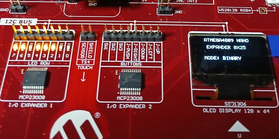
MCP23008 and OLED