
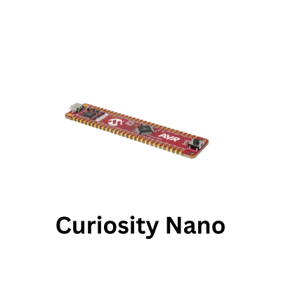
The MCP9808 is a digital temperature sensor intended for applications where more accurate temperature measurement is required than can normally be obtained from a general-purpose microcontroller’s internal temperature sensor.
It performs the temperature measurement and conversion internally, allowing the ATmega4809 to retrieve a digital temperature value over I2C.
This makes the device useful for environmental monitoring, equipment temperature measurement, data logging, thermostatic control and experiments where repeatable temperature readings are more important than simply detecting whether a system is becoming warmer or cooler.
Communication with the MCP9808 uses a conventional register-based I2C interface. The ATmega4809 can select an internal register by writing its address and then read the associated data using the TWI peripheral.
Temperature is available from the ambient temperature register as a multi-byte value that must be decoded before it can be expressed in degrees Celsius. This provides a useful example of working directly with sensor registers rather than relying on a library that hides the underlying transactions.
Other registers provide access to configuration, temperature limits, device identification, manufacturer identification and measurement resolution.
One particularly useful characteristic of the MCP9808 is its selectable temperature resolution. The sensor can be configured for resolutions of 0.5°C, 0.25°C, 0.125°C or 0.0625°C. Higher resolution provides finer measurement steps but also requires a longer conversion time, so the setting can be selected according to the needs of the application.
It is important to distinguish resolution from accuracy: a sensor capable of reporting changes in small fractions of a degree is not necessarily accurate to the size of its smallest measurement step.
The MCP9808 is specified for operation across a temperature range of -40°C to +125°C. Microchip specifies typical accuracy of ±0.25°C from -40°C to +125°C, with a maximum accuracy specification of ±0.5°C between -20°C and +100°C and ±1°C across the complete operating range. The device operates from a 2.7 V to 5.5 V supply and is designed for low-power temperature monitoring.
Three address-selection inputs allow multiple MCP9808 devices to coexist on the same I2C bus, with addresses available within the 0x18 to 0x1F range depending on the states of the address pins. A module may have these pins permanently configured or expose them through solder jumpers, so its actual address should be confirmed when connecting more than one device.
Another useful feature is the MCP9808’s programmable temperature-alert system. Upper, lower and critical temperature limits can be stored in dedicated registers, allowing the sensor to indicate when measured temperature crosses configured thresholds.
The alert output can therefore be connected to a microcontroller input so that the ATmega4809 does not have to continuously poll the temperature simply to determine whether a limit has been exceeded. Depending on the configuration, this functionality can be used for thermostatic control, over-temperature warnings, equipment protection or interrupt-driven monitoring.
The sensor also provides a shutdown mode that reduces power consumption when continuous measurements are unnecessary.
Setup
- PA2 – I2C Data for both MCP9808 & SSD1306)
- PA3 – I2C Clock for both MCP9808 & SSD1306)
- PF5 – Onboard LED (Toggles on each successful measurement)
Code
Here is the complete C code for the ATmega4809 Curiosity Nano reading ambient temperature from the MCP9808 sensor (address 0x1C) and displaying the calculated temperature in both Celsius and Fahrenheit on the SSD1306 OLED screen.
#define F_CPU 3333333UL // Default ATmega4809 clock speed (20MHz / 6)
#include <avr/io.h>
#include <util/delay.h>

// I2C 7-Bit Device Addresses
#define MCP9808_I2C_ADDR 0x1C  // Standard address for MCP9808
#define SSD1306_I2C_ADDR 0x3D  // Standard address for SSD1306 OLED

// MCP9808 Register Address
#define MCP9808_REG_TA   0x05  // Ambient Temperature Register

// Onboard LED Definition (PF5 on ATmega4809 Nano)
#define HEARTBEAT_LED_MASK PIN5_bm

// --- Font Table (ASCII 32 to 90: ' ' through 'Z') ---
const uint8_t FONT_5x7[][5] = {
    {0x00, 0x00, 0x00, 0x00, 0x00}, // ' '
    {0x00, 0x00, 0x5F, 0x00, 0x00}, // '!'
    {0x00, 0x07, 0x00, 0x07, 0x00}, // '"'
    {0x14, 0x7F, 0x14, 0x7F, 0x14}, // '#'
    {0x24, 0x2A, 0x7F, 0x2A, 0x12}, // '$'
    {0x23, 0x13, 0x08, 0x64, 0x62}, // '%'
    {0x36, 0x49, 0x55, 0x22, 0x50}, // '&'
    {0x00, 0x05, 0x03, 0x00, 0x00}, // '\''
    {0x00, 0x1C, 0x22, 0x41, 0x00}, // '('
    {0x00, 0x41, 0x22, 0x1C, 0x00}, // ')'
    {0x14, 0x08, 0x3E, 0x08, 0x14}, // '*'
    {0x08, 0x08, 0x3E, 0x08, 0x08}, // '+'
    {0x00, 0x50, 0x30, 0x00, 0x00}, // ','
    {0x08, 0x08, 0x08, 0x08, 0x08}, // '-'
    {0x00, 0x60, 0x60, 0x00, 0x00}, // '.'
    {0x20, 0x10, 0x08, 0x04, 0x02}, // '/'
    {0x3E, 0x51, 0x49, 0x45, 0x3E}, // '0'
    {0x00, 0x42, 0x7F, 0x40, 0x00}, // '1'
    {0x42, 0x61, 0x51, 0x49, 0x46}, // '2'
    {0x21, 0x41, 0x45, 0x4B, 0x31}, // '3'
    {0x18, 0x14, 0x12, 0x7F, 0x10}, // '4'
    {0x27, 0x45, 0x45, 0x45, 0x39}, // '5'
    {0x3C, 0x4A, 0x49, 0x49, 0x30}, // '6'
    {0x01, 0x71, 0x09, 0x05, 0x03}, // '7'
    {0x36, 0x49, 0x49, 0x49, 0x36}, // '8'
    {0x06, 0x49, 0x49, 0x29, 0x1E}, // '9'
    {0x00, 0x36, 0x36, 0x00, 0x00}, // ':'
    {0x00, 0x56, 0x36, 0x00, 0x00}, // ';'
    {0x08, 0x14, 0x22, 0x41, 0x00}, // '<'
    {0x14, 0x14, 0x14, 0x14, 0x14}, // '='
    {0x00, 0x41, 0x22, 0x14, 0x08}, // '>'
    {0x02, 0x01, 0x51, 0x09, 0x06}, // '?'
    {0x32, 0x49, 0x79, 0x41, 0x3E}, // '@'
    {0x7E, 0x11, 0x11, 0x11, 0x7E}, // 'A'
    {0x7F, 0x49, 0x49, 0x49, 0x36}, // 'B'
    {0x3E, 0x41, 0x41, 0x41, 0x22}, // 'C'
    {0x7F, 0x41, 0x41, 0x22, 0x1C}, // 'D'
    {0x7F, 0x49, 0x49, 0x49, 0x41}, // 'E'
    {0x7F, 0x09, 0x09, 0x09, 0x01}, // 'F'
    {0x3E, 0x41, 0x49, 0x49, 0x7A}, // 'G'
    {0x7F, 0x08, 0x08, 0x08, 0x7F}, // 'H'
    {0x00, 0x41, 0x7F, 0x41, 0x00}, // 'I'
    {0x20, 0x40, 0x41, 0x3F, 0x01}, // 'J'
    {0x7F, 0x08, 0x14, 0x22, 0x41}, // 'K'
    {0x7F, 0x40, 0x40, 0x40, 0x40}, // 'L'
    {0x7F, 0x02, 0x0C, 0x02, 0x7F}, // 'M'
    {0x7F, 0x04, 0x08, 0x10, 0x7F}, // 'N'
    {0x3E, 0x41, 0x41, 0x41, 0x3E}, // 'O'
    {0x7F, 0x09, 0x09, 0x09, 0x06}, // 'P'
    {0x3E, 0x41, 0x51, 0x21, 0x5E}, // 'Q'
    {0x7F, 0x09, 0x19, 0x29, 0x46}, // 'R'
    {0x46, 0x49, 0x49, 0x49, 0x31}, // 'S'
    {0x01, 0x01, 0x7F, 0x01, 0x01}, // 'T'
    {0x3F, 0x40, 0x40, 0x40, 0x3F}, // 'U'
    {0x1F, 0x20, 0x40, 0x20, 0x1F}, // 'V'
    {0x3F, 0x40, 0x38, 0x40, 0x3F}, // 'W'
    {0x63, 0x14, 0x08, 0x14, 0x63}, // 'X'
    {0x07, 0x08, 0x70, 0x08, 0x07}, // 'Y'
    {0x61, 0x51, 0x49, 0x45, 0x43}  // 'Z'
};

// --- I2C Engine ---
void TWI0_Init(void) {
    PORTA.DIRCLR = PIN2_bm | PIN3_bm;
    PORTA.PIN2CTRL = PORT_PULLUPEN_bm; // Enable pull-up on PA2 (SDA)
    PORTA.PIN3CTRL = PORT_PULLUPEN_bm; // Enable pull-up on PA3 (SCL)

    TWI0.MBAUD = 12; // ~100 kHz @ 3.33MHz system clock
    TWI0.MCTRLA = TWI_ENABLE_bm;
    TWI0.MSTATUS = TWI_BUSSTATE_IDLE_gc; // Set bus state to IDLE
}

uint8_t TWI0_Start(uint8_t addr_rw) {
    TWI0.MADDR = addr_rw;
    while (!(TWI0.MSTATUS & (TWI_RIF_bm | TWI_WIF_bm)));

    if (TWI0.MSTATUS & TWI_RXACK_bm) { // Check for NACK response
        TWI0.MCTRLB = TWI_MCMD_STOP_gc;
        return 0;
    }
    return 1;
}

uint8_t TWI0_Write(uint8_t data) {
    TWI0.MDATA = data;
    while (!(TWI0.MSTATUS & TWI_WIF_bm));

    if (TWI0.MSTATUS & TWI_RXACK_bm) {
        return 0; // NACK
    }
    return 1; // ACK
}

uint8_t TWI0_Read(uint8_t ack) {
    while (!(TWI0.MSTATUS & TWI_RIF_bm));
    uint8_t data = TWI0.MDATA;

    if (ack) {
        TWI0.MCTRLB = TWI_MCMD_RECVTRANS_gc;
    } else {
        TWI0.MCTRLB = TWI_ACKACT_NACK_gc | TWI_MCMD_STOP_gc;
    }
    return data;
}

void TWI0_Stop(void) {
    TWI0.MCTRLB = TWI_MCMD_STOP_gc;
}

// --- MCP9808 Temperature ---
uint8_t MCP9808_ReadTemp(float *tempC) {
    // 1. Point to ambient temperature register (0x05)
    if (!TWI0_Start((MCP9808_I2C_ADDR << 1) | 0)) return 0;
    if (!TWI0_Write(MCP9808_REG_TA)) return 0;

    // 2. Restart and read 2 bytes
    if (!TWI0_Start((MCP9808_I2C_ADDR << 1) | 1)) return 0;
    uint8_t upperByte = TWI0_Read(1); // Read upper byte with ACK
    uint8_t lowerByte = TWI0_Read(0); // Read lower byte with NACK & STOP

    // Clear alert flags from bits 13-15
    upperByte &= 0x1F;

    // Handle negative sign bit (Bit 12)
    if (upperByte & 0x10) {
        upperByte &= 0x0F; // Clear sign bit
        *tempC = 256.0f - (((float)upperByte * 16.0f) + ((float)lowerByte / 16.0f));
    } else {
        *tempC = ((float)upperByte * 16.0f) + ((float)lowerByte / 16.0f);
    }

    return 1;
}

// --- SSD1306 OLED Display ---
void SSD1306_Command(uint8_t cmd) {
    TWI0_Start((SSD1306_I2C_ADDR << 1) | 0);
    TWI0_Write(0x00);
    TWI0_Write(cmd);
    TWI0_Stop();
}

void SSD1306_Data(uint8_t data) {
    TWI0_Start((SSD1306_I2C_ADDR << 1) | 0);
    TWI0_Write(0x40);
    TWI0_Write(data);
    TWI0_Stop();
}

void SSD1306_Init(void) {
    _delay_ms(100);
    SSD1306_Command(0xAE);
    SSD1306_Command(0xD5); SSD1306_Command(0x80);
    SSD1306_Command(0xA8); SSD1306_Command(0x3F);
    SSD1306_Command(0xD3); SSD1306_Command(0x00);
    SSD1306_Command(0x40);
    SSD1306_Command(0x8D); SSD1306_Command(0x14);
    SSD1306_Command(0x20); SSD1306_Command(0x00);
    SSD1306_Command(0xA1);
    SSD1306_Command(0xC8);
    SSD1306_Command(0xDA); SSD1306_Command(0x12);
    SSD1306_Command(0x81); SSD1306_Command(0xCF);
    SSD1306_Command(0xD9); SSD1306_Command(0xF1);
    SSD1306_Command(0xDB); SSD1306_Command(0x40);
    SSD1306_Command(0xA4);
    SSD1306_Command(0xA6);
    SSD1306_Command(0xAF);
}

void SSD1306_Clear(void) {
    for (uint8_t page = 0; page < 8; page++) {
        SSD1306_Command(0xB0 + page);
        SSD1306_Command(0x00);
        SSD1306_Command(0x10);
        for (uint8_t col = 0; col < 128; col++) {
            SSD1306_Data(0x00);
        }
    }
}

void SSD1306_DrawChar(char c, uint8_t page, uint8_t col) {
    if (c >= 'a' && c <= 'z') c -= 32;
    if (c < 32 || c > 90) c = ' ';

    uint8_t font_index = c - 32;

    SSD1306_Command(0xB0 + page);
    SSD1306_Command(0x00 + (col & 0x0F));
    SSD1306_Command(0x10 + ((col >> 4) & 0x0F));

    for (uint8_t i = 0; i < 5; i++) {
        SSD1306_Data(FONT_5x7[font_index][i]);
    }
    SSD1306_Data(0x00);
}

void SSD1306_DrawString(const char *str, uint8_t page, uint8_t col) {
    while (*str && col < 122) {
        SSD1306_DrawChar(*str++, page, col);
        col += 6;
    }
}

// Convert float to fixed-decimal ASCII string (e.g. 24.25 -> "+24.25 C")
void Format_Temp_String(float temp, char *buffer, char unit) {
    if (temp < 0) {
        buffer[0] = '-';
        temp = -temp;
    } else {
        buffer[0] = '+';
    }

    int whole = (int)temp;
    int decimal = (int)((temp - (float)whole) * 100.0f);

    buffer[1] = (whole / 100) % 10 + '0';
    buffer[2] = (whole / 10) % 10 + '0';
    buffer[3] = (whole % 10) + '0';
    buffer[4] = '.';
    buffer[5] = (decimal / 10) + '0';
    buffer[6] = (decimal % 10) + '0';
    buffer[7] = ' ';
    buffer[8] = unit;
    buffer[9] = '\0';
}

int main(void) {
    // Configure PF5 as Heartbeat LED (Active Low)
    PORTF.DIRSET = HEARTBEAT_LED_MASK;
    PORTF.OUTSET = HEARTBEAT_LED_MASK;

    TWI0_Init();
    SSD1306_Init();
    SSD1306_Clear();

    SSD1306_DrawString("ATMEGA4809 NANO", 0, 16);
    SSD1306_DrawString("MCP9808 TEMP", 2, 28);

    float tempC = 0.0f;
    float tempF = 0.0f;
    char textBuf[11];

    while (1) {
        if (MCP9808_ReadTemp(&tempC)) {
            tempF = (tempC * 1.8f) + 32.0f;

            // Render Celsius
            Format_Temp_String(tempC, textBuf, 'C');
            SSD1306_DrawString("TEMP: ", 5, 8);
            SSD1306_DrawString(textBuf, 5, 46);

            // Render Fahrenheit
            Format_Temp_String(tempF, textBuf, 'F');
            SSD1306_DrawString("TEMP: ", 7, 8);
            SSD1306_DrawString(textBuf, 7, 46);

            PORTF.OUTTGL = HEARTBEAT_LED_MASK; // Toggle onboard LED
        }

        _delay_ms(1000);
    }

    return 0;
}
Image
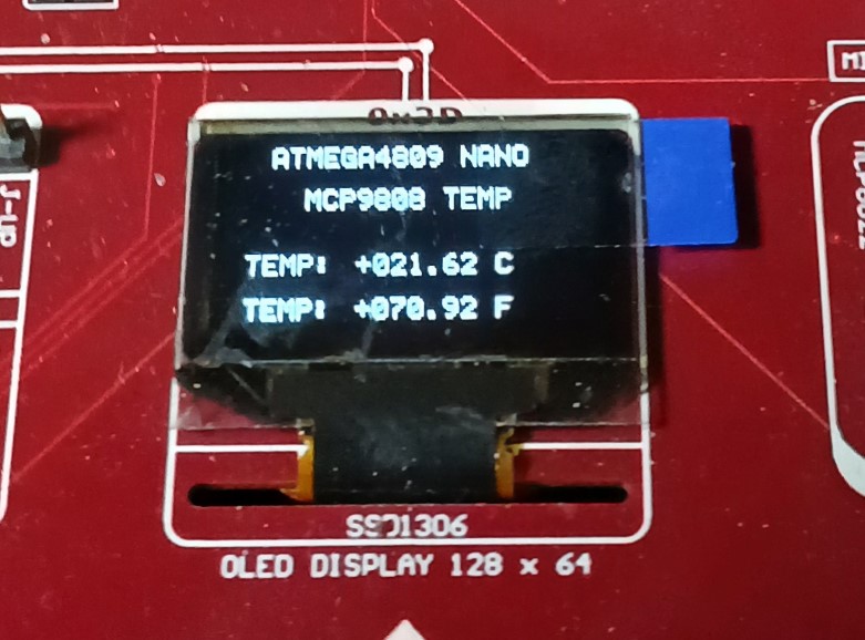
mcp9808 and oled