I recently bought a development board for an ATMEGA128, sadly there was no examples and no schematic supplied but after some trial and error I managed to get this up and running. The board came with 8 LEDs connected to PORTC and 8 switches connected to PORTB. So as a basic example I decided to write an example which when a button was pressed would light up all the LEDs and then they would all switch off.
To use a push button switch with a microcontroller, first you should configure the corresponding pin as an input. After this is done you can read the state of that pin and perform an action based on this.
In the schematic below I have shown the switch I used connected up and the LEDs, obviously you would need to power the device and also you may wish to fit a suitable crystal.
Schematic
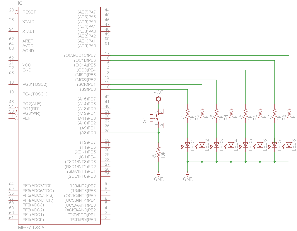
atmega128 leds and button
Code
The code was written in AtmelStudio and the board had a 10 pin ISP connector which I connected up and used a USBASP cable with a GUI to Avrdude called AVRPal.
To explain some of the terminology used below
DDR is the Data Direction Register which determines whether a pin is input or output, the PORT register is the output register which is used to write the output to pins and the PIN register is the PORT Input Register which is used to read data from the input pins
[codesyntax lang=”c”]
#define F_CPU 8000000UL

#include <avr/io.h>
#include <util/delay.h>

int main(void)
{
DDRC = 0xFF; //Makes all pind of PORTC as Output

DDRB &= ~(1<<PB0);//Makes first pin of PORTD as Input

while(1) //infinite loop
{
if(PINB & (1<<PB0) == 1) //If switch is pressed
{
PORTC = 0xFF; //Turns ON LEDs
_delay_ms(1000); //1 second delay
PORTC = 0x00; //Turns OFF LEDs
}
}
}
[/codesyntax]
Links
5PCS ATMEGA128A
Atmega128 avr development board
AVR development board ATMEGA128 development board minimum system + USB cable